dual_sport_dork 🐧🗡️

Progenitor of the Weird Knife Wednesday feature column. Is “column” the right word? Anyway, apparently I also coined the Very Specific Object nomenclature now sporadically used in the 3D printing community. Yeah, that was me. This must be how Cory Doctorow feels all the time these days.

  • 26 Posts
  • 1.38K Comments
Joined 1 year ago
cake
Cake day: July 20th, 2023

help-circle

  • Your slicer should also be able to compensate for this already.

    PLA only shrinks about 0.3% which is negligible unless you are designing with super tight clearances. A 6mm hole, for instance, will be out 0.018mm which is probably scraping against the XY resolution limits of most consumer 3D printers anyhow.

    Other materials can definitely shrink more. ABS is harder to manage than PLA, but for instance Nylon/PA’s shrink rate is comparatively immense – around 2%. The various engineering polymers that are filled with something like carbon or glass fibers actually tend to shrink less than their raw counterparts.



  • If it were me, I probably would not be able to resist the urge to make whatever inserts you develop compatible with a Gridfinity baseplate, because I am that kind of nerd.

    To create perfectly console-shaped two dimensional inserts, or at least close enough, I would start by laying each system flat on a piece of paper and tracing around it with a narrow bodied mechanical pencil. Stick this in your scanner and make an image out of it, and then trace over that image at scale in the CAD software of your choice (FreeCAD is… free). This will automatically come with a built in amount of clearance in the amount of half of the width of the body of your pencil.

    Just make a flat base with a wall sticking up maybe 2-3mm thick or more if you feel like it, to roughly half the height of each object. You can put some gaps in it if you prefer to have places to grab the item directly.


  • And for anyone who winds up struggling with this when trying to gauge their own printer, make sure this option is enabled:

    This is in Prusa/Slic3r and its derivatives. If this is disabled, the final outer wall perimeter can wind up being pushed out by some fraction of the width of the wall behind it, which will have the net effect of shrinking vertical holes in your model (and other critical clearances in the X/Y dimensions) by an unpredictable amount.


  • As long as you stay within its plastic deformation limit, “many cycles” should not matter.

    PLA’s downfall for flexible design elements is permanent deflection. It cannot be used on anything that is expected to stay in its tensioned state for anything more than a few seconds. This is why PLA works for catapults and toothpick guns and latches that have a single position rest state where the flexible element is relaxed. If you leave it under tension, though, even just for a few hours, it will not spring back fully. Eventually, it just won’t spring back at all.

    Through much testing (read: slowly pissing myself off) I determined in the course of developing my Rockhopper that ABS is the best commonly available choice for permanently or semi-permanently loaded printed spring fixtures – at least out of what most normal and sane people can print with their hobby level machines. Even PETG is better than PLA in that respect, but PLA was useless for me.


  • Y’all need to point me towards one of those tiny Linux systems. I have an old no-longer-bricked Toshiba Satellite that somebody gave me and I got it to boot again, so I slapped Mint on it to see how I liked it since I’ve never messed with that distro before. The only problem is this sucker is a dog, it’s only got 2 gigs of RAM and a pokey 5400 RPM platter drive in it. The thing sits there and thrashes swap constantly even when it’s doing nothing, and when Mint is creating one of its automated system image rollback things it’s completely unusable. I’m surprised the laptop platters don’t escape their casing and bore into the Earth like a drill bit.

    I found that it will… eventually… load and run the latest FreeCAD build and once it’s going it’s actually not bad (awful screen resolution and single touch only trackpad notwithstanding). But getting there when taken altogether takes about 20 minutes…


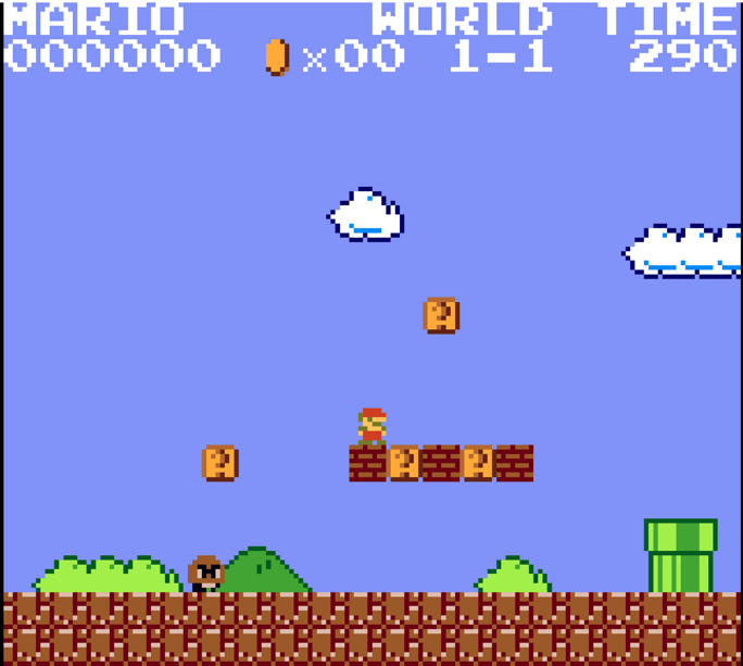
  • This port scales the graphics down to the GB’s resolution. I imagine it takes a lot of CPU cycles just to rearrange the graphics data into the Game Boy’s 8x8 tile structure in display RAM. Either that, or it’s precomputed and the ROM is huge.

    What would make anyone think they’re downscaling graphics in real time on the Gameboy of all things? The graphics have been flat out redrawn to better fit the Gameboy’s lower screen resolution.

    For anyone wondering, here’s the first little bit of what 1-1 looks like:

    Look at that doofy goomba.